 |
| AI image generated by Grok. |

Showing posts with label history of science & technology. Show all posts
Showing posts with label history of science & technology. Show all posts
Friday, November 14, 2025
Technology Tedium
Wednesday, June 04, 2025
A Vintage Flyback Transformer
 |
| Teravolt at English Wikipedia, CC BY 3.0 via Wikimedia Commons. |

These were used in TVs until cathode ray tubes (CRTs) were replaced by plasma and then LED displays. CRTs use an electron beam that traces out an image line by line on a glass screen, starting at the top left of the screen and working downwards. The path followed by the beam is just like how we read text on a page. A flyback transformer is used to produce a high voltage, in the order of tens of kilovolts, to accelerate the beam and make it strike a phosphor coating, the latter emitting light on impact. Only one point on the screen is illuminated at any one time, hence the bright spot at the centre of the screen when old TVs were powered down and the scanning coils were turned off. Persistence of vision and the 25 Hz scanning rate (50 Hz in total because of interlacing) give the impression that a complete image is displayed all at once.
Sunday, June 01, 2025
A 19th Century Light Bulb
 |
| Oliver F. Brastow, Public domain, via Wikimedia Commons. Image pixel size doubled. |

I just checked a table and actually the resistivity of iron doesn't differ hugely from that of tungsten. It's only around half the value. This would mean that a filament of the same length made from iron rather than tungsten would have half the resistance. For the same voltage applied to the filament, current would be double and the power equation would give a value for power consumption of twice that produced for a tungsten filament. Tungsten however has a higher meting point and can become white hot in a lamp, without melting or losing its integrity on supporting wires.
Thursday, May 29, 2025
The First White LED
 |
| Public domain image courtesy sinisamaric on Pixabay. |
Friday, May 23, 2025
IBM Disk Drives
 |
| User RTC on en.wikipedia, Public domain, via Wikimedia Commons |

In
the foreground, two IBM 350 disk drives, each with a capacity of 3.75
MB and consisting of a stack of fifty two, 24 inch disks. Production
began in 1957. It wouldn't be possible to store even one photo from a
smartphone on such a drive and the capacity is a little over 2.5 times
the storage space of the 3 1/2" floppy disks that became available in
the late 1980s. Those disks replaced the earlier, lower capacity 5 1/4"
disks. (I used 8" floppy disks on a microprocessor development system.
This was the first format of portable floppy and became commercially
available in 1971).
Sunday, March 16, 2025
Hear Today, Gone Tomorrow
Remember
when you were young and could hear the high pitched whine of the
horizontal line scan transformer in a TV that was using the 625 line
system? The line output or LOPT transformer operated at 15,625 Hz, and
you could tell that the TV was turned on, even with the sound turned
down. Before that in the early 70s, vertical resolution was 405 lines.
Young children can hear up to a frequency of 20 kHz. Most of us over 50
can only hear to 10 kHz.
Public domain image courtesy Pexels.
Wednesday, February 26, 2025
Trivia Alert! — "AAAA" Size Battery
 |
| AA batteries. © Eugene Brennan |
Ray Darcy was going on about random stuff as usual today and we heard some trivia about quadruple-A or "AAAA" batteries. These are a bit shorter and narrower than an "AAA" cell, and used for slim devices like styluses, laser pointers, penlights and glucose meters. There was also a single-A cell that is now obsolete and also a newer "A" cell and fractional "AA" cells.
This comprehensive Wikipedia article lists all the various battery sizes, both still used and obsolete.
Sunday, January 19, 2025
All Shapes and Sizes
 |
| A variety of 9 V batteries. Image courtesy Lead holder, CC BY-SA 4.0 via Wikimedia Commons. |

Nowadays,
if you go to a shop to buy batteries, apart from the coin cells, the
chances are you'll only have five types to choose from, if even that.
Those are the AA, AAA, C and D sizes and the small, square 9 Volt PP3
(Also designated as type MN104 or 'E'). In the 70s, there were a
multitude of battery types, now pretty much obsolete or hard to come by.
So in addition to the PP3, there were several different sized 9 V
batteries with different capacities, made for powering portable
transistor radios and other electronic appliances. A 6 V battery with
two spring terminals on top was available for powering lantern type
torches with handles, and a smaller 4.5 V battery (3LR12) with two, flat
springy brass terminals on top was available for slim, flat pocket
torches. The cylindrical, handlebar-mounted style of bicycle lamp we use
today hadn't been invented or at least wasn't common and Ever Ready
bicycle lanterns were more the norm. These were powered by a 3 V No.
800 battery, composed of two, 1.5 V cells in series, the two cells
arranged side by side, with springy brass terminals. Other types of
batteries included the U14 for gas lighters and Ever Ready 3V No. 8
batteries (not sure what these were for, possibly small torches).
What's the difference between a cell and a battery?
Cells
work on the principle of potential differences created between
dissimilar metals or other material (e.g. carbon) placed in an
electrolyte (a chemical solution, paste or gel). So for instance one
type of cell technology is the Leclanché cell. This is a wet cell (using
a liquid electrolyte) invented in the 19th century, The dry version of
the Leclanché cell is the zinc carbon "battery" which we used before
alkaline batteries became widely available in the late 70s and early 80s
under the Duracell and Energiser brands. Cells only produce around 4
volts maximum (for lithium ion) and 1.5 volts for alkaline or zinc
carbon. To get higher voltages, we connect cells in series in a chain,
so the voltages add up. We call the collection of cells a battery.
A car battery has six cells connected in series to give a nominal 12
volts. Each cell produces 2 volts nominally. (In reality a fully charged
car battery gives out over 13 volts).
This Wikipedia article lists all the current and obsolete battery types, giving details about their uses.
Image courtesy Lead holder, CC BY-SA 4.0 <https://creativecommons.org/licenses/by-sa/4.0>, via Wikimedia Commons
Sunday, November 17, 2024
Reverend Nicholas Callan and the Induction Coil
 |
| Rev. Nicholas Callan. Public domain image via Wikimedia Commons: https://en.wikipedia.org/wiki/Nicholas_Callan... |
The device is a type of
transformer, commonly used in vehicles in the form of an ignition coil
for generating the tens of thousands of volts necessary to create a
spark at the plugs. Induction coils with an output of hundreds of
thousands of volts were used for early spark-gap transmitters. Connected
to a tuned circuit and antenna, they could transmit radio waves at a
certain frequency. The tuned circuit is the electrical analog of a bell.
A spark discharge "rang" the bell by setting off electrical
oscillations.. These transmitters would have been used for
intercontinental and ship-to-shore communications in the era of the
Titanic.
Electromagnetic Induction
Electromagnetic
induction is a phenomenon discovered by the English scientist Michael
Faraday in 1831. If you move a magnet close to an electrical conductor,
e.g. a looped piece of wire, the field of the magnet induces an electric
current in the wire. It's the change in magnitude of the magnetic field
that creates the current, rather than the fact that the magnet is
moving. If the field is constant in magnitude, no current is induced.
The magnitude of the voltage that creates the current is proportional to
the rate of change of magnetic flux, in other words, the faster the
magnetic field changes in size, the greater the voltage.
How Do Transformers Work?
All transformers and electrical generators work on the principle of electromagnetic induction.
The
transformers such as those used in older power adapters and corded
electronic equipment have a laminated core, made of a stack of
wafer-thin, soft iron sections, insulated from each other. A primary
coil wound around the core (hundreds of turns of wire) generates a
fluctuating current when connected to an AC mains source. This in turn
creates a fluctuating magnetic field and that field then induces an
electric current in a secondary winding. A transformer simply increases
voltage, or decreases it, like the room sized transformers we have at
the sub-station in Kilcullen. The ratio of the number of turns of wire
on the primary coil to those on the secondary coil, known as the turns
ratio, determines the factor by which the output is increased or
decreased. So if the input coil has 1000 turns and the secondary coil
has 100 turns, that's a turns ratio of 10 and voltage is reduced by a
factor of 10
 |
| Schematic of a transformer. Image author BillC at the English-language Wikipedia, CC BY-SA 3.0 |
What are Induction Coils?
Instead
of being fed by AC, an induction coil works on DC. It has a primary
coil with hundreds of turns of wire and a secondary with thousands of
turns. The coil when energised also acts like an electromagnet. This
isn't the case with a standard transformer because the iron core is in
the form of a closed loop, with no external field. The DC source, e.g. a
battery, is connected to the coil via a spring switch, called an
interrupter, that can be opened and closed by the force of the
electromagnet (the same mechanism is used on old doorbells). On
connection of the supply, with the switch closed, the magnetic field in
the core grows until the electromagnet suddenly opens the switch,
disconnecting the input. The magnetic field rapidly collapses and it's
this rapid collapse and change in field that induces a huge voltage in
the secondary, much greater than the turns ratio could produce with an
AC source. When current is disconnected by the switch, the force of the
electromagnet drops to zero, causing the spring to close the switch
again, reconnecting the circuit and the cycle repeats indefinitely,
generating high voltage pulses at the rate of hundreds per second.
 |
| An induction coil. Image courtesy Hannes Grobe, CC BY 3.0 via Wikimedia Commons |

More information on Rev. Nicholas Callan on the Maynooth University website here:
Wednesday, October 23, 2024
Kildare DC Electric Station
 |
| Image courtesy Brian Murphy, KILDARE DC ELECTRICITY STATION, Cill Dara Historical Society: Kildare Town Heritage Series No. 37 (https://www.facebook.com/kildaretownfootprints/posts/147252716928373) - Accessed 16/10/24 |
Nowadays
we use natural gas in our homes and industry. It comes from natural gas
deposits such as the offshore Corrib gas field off the coast of Mayo
and previously from the Kinsale Head gas field which is now depleted. We
also import gas from the UK and mainland Europe through several gas
interconnectors. Natural gas is pretty much odourless methane, with an
odoriser added for safety reasons.
Coal gas
Before
the advent of natural gas, cities and many towns had their own
gasworks. Coal was roasted to create a gas which could be stored in
large tanks called gasometers and coke and tar remained as by-products.
Tar could be used for road building and coke used as a fuel domestically
or in foundries for smelting iron ore.
The Kildare DC Electricity Station
In
the Kildare station, just like in a gasworks, gas was produced from
coal in a gas plant room. The article doesn't mention how the liquid
fuel was obtained, but presumably the gas that was created from roasted
coal was distilled and condensed to a liquid that could be stored and
used to power the engines. This process known as gasification isn't
limited to coal as a raw product. In fact any biomass can be used that
contains cellulose, such as wood chip. During WW2 when there were fuel
shortages, modified "wood gas cars" and buses ran on such fuels, with an
onboard or towed gasifier generating the fuel gas.
This article about the Kildare DC Station by Brian Murphy was first published in the Kildare Nationalist in 2009.
Wednesday, August 28, 2024
Automatic Telephone Exchanges
 |
| A panel of stepping switches at a telephone exchange. Public domain image via Wikimedia Commons. |

In
Ireland, unlike the UK, we skipped having transistorised telephone
exchanges and went straight from electromechanical (using relays, coils
and motors) step-by-step or more modern crossbar systems to digital
versions. When I was in the boy scouts in the 70s, I remember the
whirring and clicking coming from the small telephone exchange building
adjacent to our den (located in the tennis club building), as the
exchange switched calls. Electrical pulses from a subscriber's telephone
(known as pulse dialling, now replaced by tone dialling)
caused a shaft on one of the mechanisms in the exchange to turn by a
varying angle, the angle depending on the number of pulses. Each number
from 0 to 9 on the dial of a telephone handset generated a different
number of pulses. The shafts on the mechanisms in the exchange had an
arm or arms attached, with electrical contacts on the end of the arm. As
the arm swept around (usually limited to a half circle), it made
contact with another set of stationary contacts, the process enabling a
call to be connected to another number locally. Trunk calls to another
"area code" would be sent to the exchange in Naas to be distributed to
other local exchanges. From what I recall, in the early 70s, either
Byrne's supermarket in Kilcullen or Athy still had a handset without a
rotary dial, sitting near the meat counter at the back of the shop,
presumably dating back to before the days of the automatic exchange.
This is an RTE report from 1989 about the changeover.
Saturday, August 17, 2024
How Kilcullen Gets Its Power and Poulaphouca Dam
 |
| Construction of the Poulaphouca Dam. Image courtesy O'Dea Photograph Collection, The National Library of Ireland. Photographer James O'Dea |
The
Liffey Reservoir Bill was signed into law and became an act in 1936.
Construction of the dam commenced in 1937 with flooding of the Liffey
Valley beginning in 1940. The hydroelectric power station was finally
commissioned in 1947.
How Does the Dam Work?
The dam simply builds up a pressure head,
similar to that produced by the weir that used to be located north of
the bridge in Kilcullen, water being kept at a high level so it gains potential energy and can release that energy to do useful work as it falls. Work
has a specific meaning in physics and is defined as "when a force moves
a body through a distance". In this case, work is done when water
loses momentum and creates a force as it decelerates on hitting turbine
blades (just like a hammer head hitting a nail). Water is carried from the dam, under the N81, to the powerhouse of the Poulaphouca Hydro Station, located several hundred metres away, via a 400 m long, 4.8 m diameter pressure tunnel and then through two penstocks, or intake tunnels, to the turbines. Two 15 MW Kaplan turbines at the generating plant produce electricity
which is stepped up to a high voltage for transmission to a 110 kV
substation near Stratford-on-Slaney.
How Does Kilcullen Get Its Power?
The
Stratford substation supplies electricity at 38 kV to the substation in Kilcullen.
From this station, power is then distributed at a lower 10 kV to
pole-mounted transformers (or cabinets in newer housing estates) around
the town which finally reduce voltage to 230 V for domestic use. 10 kV lines can be radial but sometimes travel out in an open ring from a substation. So if there's a fault or break in a line, one part of the line can be isolated in order that other houses on the ring can still be supplied with electricity. (The open ring is closed.) At a transmission level (110 kV and higher) the
idea of an electricity grid is to build redundancy into the system so that power can find its way around "holes" in the grid (analogous to a
fishing net). So if for instance Poulaphouca hydroelectric station
becomes non-functional, the transformer station at Stratford is fed
from elsewhere. Similarly, Kilcullen is connected to the Newbridge 110 kV station via the Athgarvan 38 kV Substation. Normally, this connection is open to reduce fault currents propagating through the grid. However, if Stratford can't supply, it's switched out of the system and Newbridge is connected to the Kilcullen station. Eirgrid, who
control the transmission network for lines of 110 kV and over, can
switch and sync generating stations into and out of the grid as demand
rises and falls. ESB Networks meanwhile are responsible for the distribution network of 38 kV and lower.
This is a map of the high voltage transmission network (high voltage being anything greater than 20 kV)
Image courtesy O'Dea Photograph Collection, The National Library of Ireland. Photographer James O'Dea
Thursday, July 25, 2024
Iconic Items in the Science Museum, London
Some photos of iconic items in the Science Museum, London, taken when I was there in 2017: The Apollo 10 command module "Charlie Brown", complete with the effects of re-entry on the underside, A Saturn V second-stage engine, a cut-away of a Parsons steam turbine, and "Puffing Billy", the world's oldest steam locomotive.
 |
| Apollo 10 capsule "Charlie Brown" in the Science Museum, London © Eugene Brennan |

 |
| Underside of Apollo 10 capsule "Charlie Brown" © Eugene Brennan |
 | ||
| Saturn V second stage engine © Eugene Brennan |
 |
| Parsons steam turbine © Eugene Brennan |
 |
| "Puffing Billy", the world's first steam locomotive © Eugene Brennan |
Wednesday, June 26, 2024
Remembering Ernest Walton: Splitting the Atom
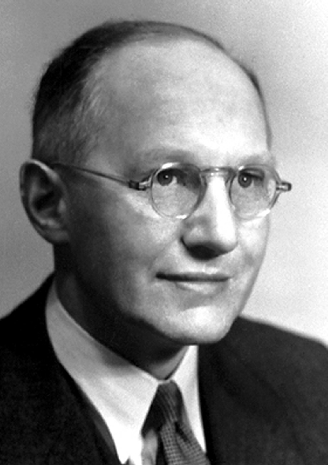 |
| Ernest Walton. Nobel foundation, Public domain, via Wikimedia Commons |

On 25th June, 1995, Ernest Walton, our only Nobel laureate for physics died in Belfast at the age of 91. Together with his colleague John Cockcroft, they built one of the first particle accelerators at the Cavendish Laboratory in Cambridge in the 1930s. This ultimately led to what's generally known as "splitting the atom". For this work, he was awarded along with Cockcroft a Nobel Prize in 1951.
Walton came to visit us in DIT, Kevin Street in Dublin when I was an engineering student there in the mid 80s, and gave a lecture during which he spoke about his work in Cambridge. He appeared to be a mild mannered and unassuming man. I'm ashamed to say I didn't know who he was at the time. It was in an era before the Internet and our education system was hardly informative either. History books told us about the figures involved in revolution and the struggle for independence, but shamefully left out Walton, Hamilton and others involved in scientific discovery. I wish I could remember the content of Walton's lecture. I vaguely remember him talking about Ernest Rutherford, the New Zealand scientist who was also a pioneering researcher in the field of nuclear physics and radioactivity from the end of the 19th century onwards. Rutherford apparently had a larger than life personality and Cockcroft and Walton, his research students, used to wind him up.
 |
| Editorial image courtesy and by permission of Guy Heilenman, Timothy Hughes Rare & Early Newspapers |
Wednesday, May 29, 2024
The Beginning of Radio Communication
 |
| Photo © Eugene Brennan |
From one of the old books that belonged to my grandfather. A note in the appendix of a volume of the ICS reference library, 1905. If only they knew the developments that were to come in the future! In modern parlance, "the high-frequency transmission wave" is known as a carrier and the modification of the carrier by the superimposed wave is known as modulation. Sound waves having frequencies in the audible spectrum can't just be converted to an equivalent radio signal and transmitted. The frequency would be too low and for various technical reasons, including providing sufficient bandwidth for other channels broadcasting on and sharing the radio spectrum, and minimizing the size of antenna required, a technique called modulation is used. This is commonly either either amplitude modulation (AM) or frequency modulation (FM). The carrier is varied by a modulating signal derived from e.g. an amplified signal from a microphone, which changes the carrier's "size" (amplitude) or frequency. Originally, carriers were low, in the hundreds of kHz or somewhat lower. Carrier frequencies nowadays are vastly higher, typically 5 gigahertz (GHz) for WIFI and up to 108 MHz for normal radio broadcast programs on the FM band.
 |
| Photo © Eugene Brennan |
Friday, February 23, 2024
Electromagnetic Induction and the Force on a Conductor in a Magnetic Field
 |
A varying electrical current in the coil on the left produces a fluctuating magnetic field. This loops through the coil on the right, inducing an electrical current. Image by Ponor, CC BY-SA 4.0 via Wikimedia Commons. |

Two principles, discovered in the early 19th century on which motors, generators and transformers work.
Electromagnetic Induction
Move
a conductor (e.g. a piece of wire) in a magnetic field (produced by a
magnet), or move the field and keep the conductor stationary or thirdly,
vary the strength of the field. The result is that a current is induced
in the conductor. This is how all electrical generators and
transformers work, electricity being induced or generated in coils of
wire as a magnetic field varies in strength. It's the main reason too
why we use AC electricity for distribution.
Force on a Conductor in a Magnetic Field
Pass
a current through a conductor placed in a magnetic field. The conductor
experiences a force which tends to push it. This is the principle on
which electric motors work.
Several
scientists in the early 19th century made fundamental discoveries about
the nature of electric currents and magnetic fields. Two of these were
the Danish physicist Hans Christian Ørsted and the English scientist
Michael Faraday. Faraday's apparatus including a transformer and motor
can be seen in the Faraday Museum at the home of the Royal Institution
in London.
Subscribe to:
Posts (Atom)